x
... loading movie ...
2014 is primed to be another great year for PC gamers. Last year saw the release of blockbuster titles like Metro: Last Light, Tom Clancy's Splinter Cell Blacklist, Call of Duty: Ghosts, Batman: Arkham Origins, and Assassin’s Creed IV: Black Flag and this year we’ll be eagerly anticipating the arrival of Everquest: Landmark, Diablo III: Reaper of Souls, Titanfall, The Elder Scrolls Online, Watch_Dogs, Dying Light, and more.
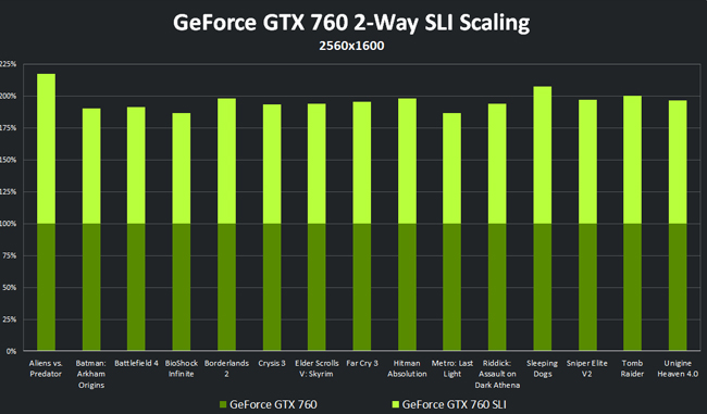
Many of the listed games leverage cutting-edge technologies like HBAO+, TXAA, GPU-accelerated PhysX, and DirectX11 tessellation to greatly enhance visual quality and realism. At the most popular gaming resolution, 1920x1080, these settings can be enabled on the vast majority of GeForce GTX GPUs. Cranking up the resolution, however, significantly decreases frame rates, necessitating the need for more powerful hardware.
For gamers, the most effective path for attaining higher performance is to add a second GeForce GTX graphics card to a new or existing PC, creating a SLI configuration that can more than double frame rates in supported titles.
Not sure how? Don't worry! We'll walk you through the whole process of building your own supercharged SLI gaming PC in two distinct installments, going all the way from starting a parts list to playing your favourite games and everything in between, with photos and descriptions for each step.
Hardware-focused, beginning with selecting the best parts for our PC, preparing ourselves and our workspace before handling our new parts, walking through the process of assembling your new PC, giving a few pointers of managing interior cables, and finally, powering our machine up for the very first time.
Software-focused, kicking off with looking through the BIOS, installing our operating system, choosing the right GeForce graphics drivers, learning about the NVIDIA Control Panel and how to tweak it for our benefit, installing some useful programs and utilities, and wrapping everything up by going over some good benchmarking practices to guarantee we'll have comparable results between different settings and components.
Before you begin selecting the components for our build, it's highly recommended that you review our PC Components Guide. If you're new to building computers it'll give you a excellent understanding of how the major system components work, the ways in which they can be different, and how to determine what will be appropriate for your needs.

Which GeForce GPU is right for you will depend on a few things, including your budget, but we'll get to that in a moment. When looking to purchase a new GPU, a few things to be mindful of include: the type and number of power connectors required, the minimum power supply capacity suggested, the size of the cooler, and the length of the card. You can expect that most graphics cards will fit into a PCI Express (commonly referred to as PCIe) slot, and will require one or two power cables to be plugged in using either 6-pin or 8-pin connectors.
This build will feature two reference PNY GeForce GTX 780 graphics cards in SLI. These Kepler-based GPUs are fully compatible with DirectX 11 and come equipped with NVIDIA-exclusive technologies like PhysX, HBAO+, SLI, Adaptive VSync, 3D Vision, GPU Boost 2.0 for on-the-fly performance boosts, and an adaptive fan speed controller that smoothens out fan speed changes to reduce noise without sacrificing cooling. NVIDIA's invaluable GeForce Experience application will be able to automatically configure the graphics settings for many popular games, assuring that you'll get the most out of your system. Being a "reference" design means that these GTX 780s have not been overclocked (set to run faster than normal) and use the GTX TITAN-style heatsink assembly designed by NVIDIA. Factory-overclocked versions and those with non-reference heatsinks are available from multiple manufacturers including ASUS, Gigabyte and EVGA.

Modern CPUs are fast, efficient, and use multiple cores to help with juggling these tasks at the same time, so you don't necessarily have to spend big bucks to get a good return on your investment. However, you do need to be mindful of which socket it is designed for (e.g. Intel's LGA 1150) so that you may find a compatible motherboard. Some processors do not come with a heatsink fan (a set of metal fins that sits on top of the CPU with a fan blowing air across to keep it running cool,) meaning you will need to find and purchase an aftermarket cooler on your own. Do not ever attempt to turn on a computer without a heatsink and thermal paste installed on the CPU! We'll be looking at how to install a CPU cooler in the next issue, so stay tuned if you're curious on how to do this.
With SLI it is very important that your CPU is able to prepare frame data and pass it off to the GPUs as quickly as possible in order for you to get the highest level of performance. If the CPU is too slow to sufficiently keep the GPUs busy, you'll become CPU-limited - that is, your performance becomes limited by the CPU, which dampens the performance gains seen by the second GPU. This build will use Intel's Core i7-4770K 3.5 GHz quad-core CPU, their newest flagship Haswell-based processor. It sports Intel's Hyper-Threading tech that splits each of the four cores virtually into two, a newer incarnation of their auto-overclocking logic called Turbo Boost 2.0 that can boost the clock speed up to 3.9 GHz, and multiple low-power states for better energy efficiency compared to previous architectures.

Just because your CPU comes with a heatsink fan doesn't mean you have to use it. If you're serious about overclocking your CPU for increased performance, there are hundreds of different aftermarket coolers made by dozens of manufacturers that can all radically reduce operating temperatures. Many of them rely on air cooling, but enthusiast-level coolers occasionally come in the form of all-in-one liquid cooling systems that are preassembled and ready to go right out of the box. Find one that matches your CPU socket, will be installable inside your case and won't push against your memory modules or prevent them from being installed, and you'll be good to go. Typically, these come bundled with a syringe of thermal paste, which is used to maximize surface contact between the cooler and the processor.
Keeping your components cool will help them work longer, more stably, and opens up the possibility of overclocking. The Cooler Master Eisberg 240L Prestige is a compact and competitive contender in the all-in-one cooler market with intuitive expansion and maintenance options, multiple speeds for the pump and fans to suit a wide range of sound and temperature preferences, and at the time of this writing holds the #1 performance slot according to Guru3D for a i7-3770K at 4.6 GHz with 1.2V core at full load (and when the voltage is increased to 1.3V it's still only 1C behind the cooler at #1, the noisier NZXT Kraken X60 Extreme.)

Desktop memory modules come in four varieties. DDR3 is the current standard type, but it will eventually be replaced by DDR4. The motherboard will only support one type of memory, and a memory module cannot be installed in a slot meant for a different type (e.g. DDR3 cannot be installed in a DDR2 slot, and vice versa.) Some high-end memory modules come with heatsinks that can be rather tall, so be weary of this if you have a large CPU cooler installed as they may not be enough clearance for one to be properly installed.
To keep the system snappy we'll use two Kingston HyperX Black 4 GB DDR3 modules (for a total of 8 GB) running at 1600 MHz in dual channel mode. These come with eXtreme Memory Profile (XMP) support for set-and-forget overclocking, have reasonably tight timings, and are dressed in matte black low-profile heatsinks.

Given its inherent complexity, attention to detail is very important when selecting a motherboard. Be sure that the one you select will physically fit inside of your case while still offering the core features you’re looking for, like a matching CPU socket, slots for all of your RAM modules, high-speed SATA ports for your storage and optical drives, and an SLI certification.
The backbone of this system will be an ASUS Maximus VI Extreme, ASUS's flagship motherboard based on the Intel Z87 chipset bearing an Intel 1150 CPU socket, four DDR3 slots for memory, 5 PCIe slots and a PLX chip providing 4-Way SLI support.
Other features include high-definition 8-channel audio, a UEFI BIOS packed with tweaking and control options, special hardware to optimize performance and save power, and painless overclocking capabilities.

Given that the whole system depends on the power supply to keep everything working, you'll have to choose your PSU carefully. Sustained output capacity is measured in Watts, and you should always aim above your needs to ensure that your PC runs uninterrupted. (This will also lend the possibility of being able to re-use the same PSU in a future PC build, but don't plan around this specifically). Beyond that, make sure the power supply you're looking at will physically fit into your case, the cables will be long enough to reach the other components in your case (or purchasing extender cables is within your budget), and there will have enough power connectors for all of the components. If the PSU has a fan built in, take note of how it will be positioned when installed; it needs to breathe so it won't overheat during operation.
Driving the system will be a Cooler Master V1000, a 1000W 80 PLUS Gold-rated, high-efficiency unit with a fully modular design that lets you save space by removing unneeded cables. It also has a large and quiet cooling fan, flattened cables that make cable management extremely simple, and it's all in a minimalistic matte black finish that won't break up our color scheme as many other power supplies are liable to do.

Try to not get torn between picking sides; combining a large HDD with a super-fast SSD is often going to provide the best results. We'll enjoy a massive speed-up by loading the operating system, our games, and our applications onto the SSD, while the HDD will hold the things that wouldn't benefit from being on a faster driver: documents, pictures, videos, and the like. Full system backups can also be stored on the HDD to take out some extra insurance against data loss. Whatever you decide to buy, be sure that the total overall storage capacity is more than you need currently, your motherboard has enough ports of whatever type the drives use (typically SATA,) your case has enough drive bays to install them, and that your power supply has enough connectors.
We'll have a pair of very fast Kingston 3K 120 SSDs running our operating system, applications, and games. They're completely silent, require very little power, and are rated by Kingston to have read/write performance above 500 MB/s. Supporting the SSDswill be a 2-TB mechanical drive for all of our documents, media, and regular system images which will minimize data loss in the unlikely event of an SSD failure. This will be brought in from a previous build - something you could easily do with your existing drives.

Enclosures are a product of both function and form. They protect your hardware from dust and accidents, pull in cool air while exhausting warm air, and provide an organized layout to optimize cable management and airflow. They also give your build its sense of personality and style, so it's a matter of finding one that will suit your needs as well as your personality.
Cases come in all sizes, and some are purpose-made to be portable for LAN parties and the like, but at the very least you'll need to make sure that your motherboard and graphics card(s) will fit inside and that there will be enough hard drive bays. If you're using a liquid cooling unit like Cooler Master's Eisberg, be doubly sure that you'll have space to mount the radiator (a block of fins that removes heat from the liquid in the cooling system) as well as the fans that attach to it..
Holding everything together will be the Cooler Master Storm Trooper, an all-black steel "full tower" enclosure that will accommodate large components (like E-ATX motherboards and long graphics cards.) There's also space behind the motherboard tray and several cut-outs for cable management, two sturdy handles on top to make transporting your fully-loaded case easier, several dust filters and meshes to keep incoming air clean, and some thoughtful design elements like a built-in drawer for tools, push-button fan speed controls, and rotatable, removable drive cages.
Finally, let's see how everything adds up. Two other SLI builds aimed at lower budgets are included as well, but don't mistake them for a slouch; these machines will be excellent performers at 1920x1080, the most common desktop resolution according to the latest Steam Hardware & Software Survey.
Due to differences in necessity and preference you'll still need to choose your own monitor(s), operating system, keyboard, mouse, optical drives, and audio equipment.
|
DIY: SLI |
Price |
DIY: SLI |
Price |
DIY: SLI |
Price |
Graphics Cards |
2x EVGA GeForce GTX 660 |
2x PNY GeForce GTX 770 |
2x PNY GeForce GTX 780 |
|||
Processor |
Intel Core-i5 3570K |
Intel Core i7-3770K |
Intel Core i7-4770K |
|||
CPU Cooler |
Cooler Master Hyper N520 |
Cooler Master Eisberg 120L Prestige |
Cooler Master Eisberg 240L Prestige |
|||
Memory |
Kingston HyperX Black 8 GB |
Kingston HyperX Black 8 GB |
Kingston HyperX Black 8 GB |
|||
Motherboard |
ASUS P8Z77-V LK |
ASUS P8Z77-V |
ASUS Maximus VI Extreme |
|||
Power Supply |
Cooler Master V700 700W |
Cooler Master V850 850W |
Cooler Master V1000 1000W |
|||
Storage |
Western Digital Black 1TB |
Kingston 3K 120 |
2x Kingston 3K 120 |
|||
Case |
Cooler Master HAF 922 |
Cooler Master Storm Trooper |
Cooler Master Storm Trooper |
|||
Total |
|
$1,191.40 |
|
$1,780.52 |
|
$2,482.84 |
NOTE: Online prices were correct at the time of writing, but will be subject to fluctuations at any time.
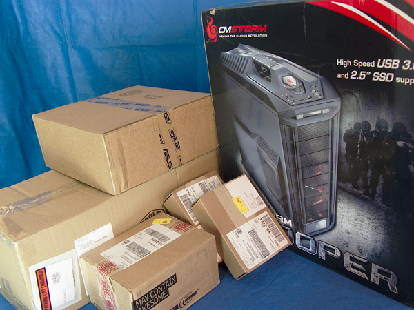
When the last of your parts arrive, you'll probably be quite eager to start ripping packages open and get started with assembling your machine. However understandable, you'll have a much better and easier time if you take a moment to prepare yourself, your workspace, and your tools first.
For the unboxing portion of the guide, we won't be looking at every item included in the package or diving too deeply into every little detail or feature, but the major bits will be covered. These are retail versions of these products, so everything you see is how it's likely to be delivered on your doorstep. If you're interested about something a particular part does that isn't talked about here, visit the links included on previous pages to learn more about pricing, features, and technical specifications.
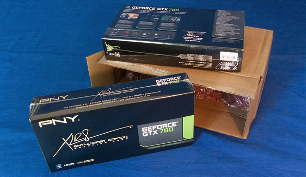
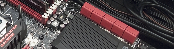
The two PNY GeForce GTX 780s arrive as slim, minimalistic boxes covered with technical features, system requirements, warranty information, and various promotions of other PNY products.
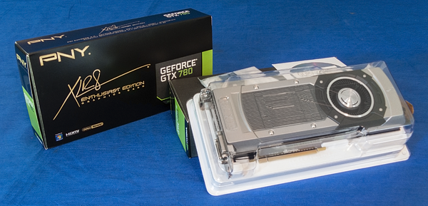
The graphics cards themselves are safely immobilised inside of a hard plastic shell. A driver CD and DVI-to-analog adapter are included, along with an instruction booklet, however it should be noted that these do not come with power connector adapters. Each card has one 8-pin and one 6-pin power connector, so if you're using a power supply different from the one mentioned in this guide please verify that you'll have the appropriate cables and connectors to power these cards.
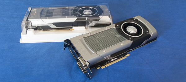
The cards themselves are pretty much ready to go when you remove them from their plastic case, although the clear window on the heatsink shroud does have a thin protective film you should remove before installation. You can see a few of the bubbles trapped under the film on one of the cards shown above. Remember to use caution when handling these or any other pieces of hardware - don't touch any of the golden connectors or circuit board components, hold it firmly by the edges, and be very careful about how you set them down on a surface.
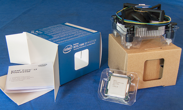
The Intel Core i7-4770K comes tightly nestled in a hard plastic clamshell, which is where it shall remain until the moment we're ready to install it on the motherboard. For the retail version (shown here), Intel includes a heatsink of its own design with a pad of thermal paste already applied to it and an installation booklet. The OEM version will only include the processor, not the heatsink or fan.

The Corsair Eisberg 240L Prestige and its accessories sit in molded cardboard and protective plastic. The cooler comes with two 120mm fans, two black rubber dampeners to minimize fan vibrations, an installation manual, and a small baggie full of screws and CPU mounting adapters, and a tiny syringe of thermal paste. We recommend using this thermal paste when installing the cooler, as it's of better quality than Intel's and will keep the CPU running slightly cooler.
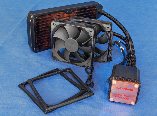
As you can see, the cooler arrives pre-assembled: the radiator, hosing, and CPU block are all firmly connected together, and the unit has been filled with coolant that will never need to be replaced. Apart from removing the protective sticker on the CPU block (which should stay put until you're ready to install it,) all you have to do is mount it some place, secure the fans, and plug in power cables, and you're set to go.
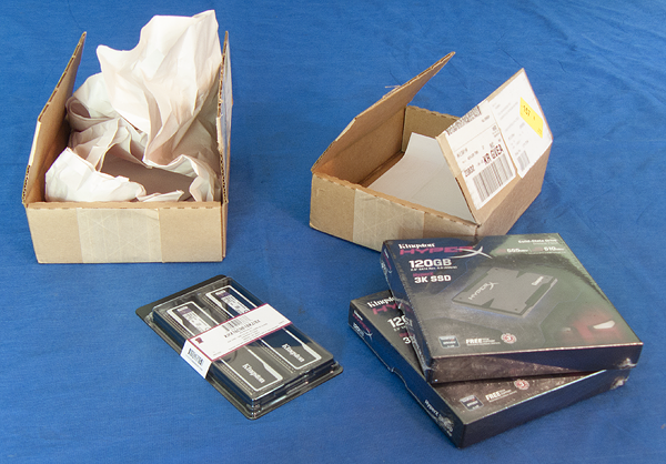
Our Kingston memory kit and the two 3K 120 SSDs.
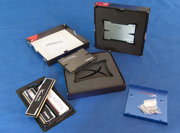
The memory modules come with nothing else except a small instruction sheet, since that's all that's necessary. The 3K drives are nestled in firm foam, bundled with a 3.5" bay adapter, two bags of screws, and an instruction manual.
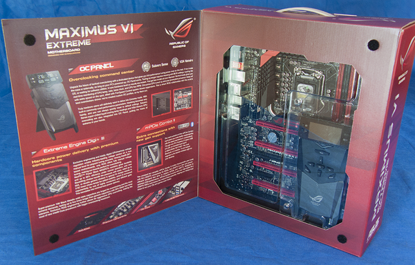
The ASUS Maximus VI Extreme ships everything packed together in a single box. A cover on the front flips over to reveal explanations of some of the motherboard's newer features, like the OC Panel and dual-band wireless mPCIe adapter (for connecting to wireless networks without occupying a standard PCIe slot or USB port), and on the other side is a window which gives a clear view of the motherboard itself. Just in front of the motherboard is the OC Panel instrument, a real-time monitoring and tweaking device that can be used as a handheld instrument or be installed in a 5.25” bay for relaying information like boot status, error codes, your CPU temperature, fan speeds, and CPU clock information. If you plan on overclocking your CPU, this will be very useful to you.
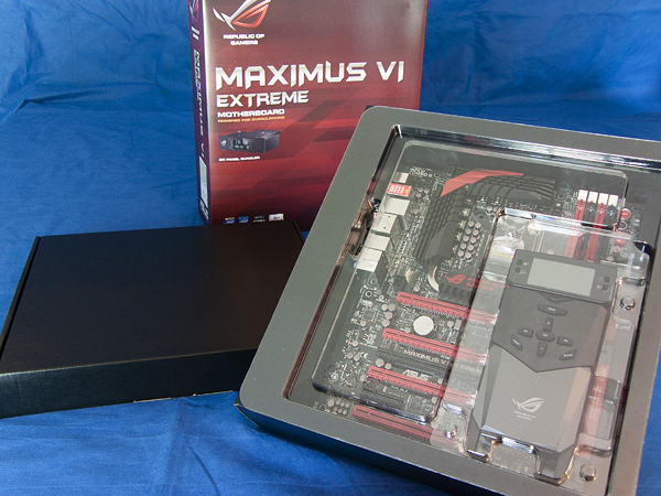
Inside you'll find the motherboard in its own tray with the OC Panel secured in an additional hard plastic clamshell.
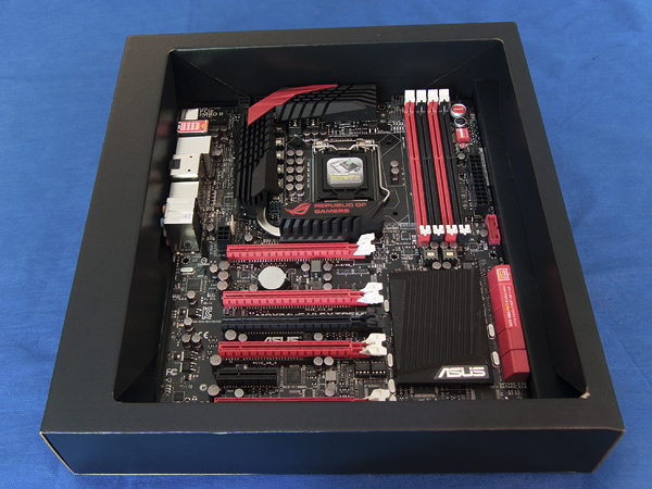
The ASUS Maximus VI Extreme in its tray. There is a protective cover sitting on top of the CPU socket which needs to stay in place until we're ready to install the processor.
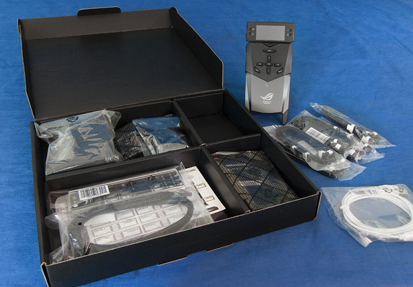
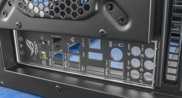
The slim black box contains all sorts of cables and connectors, a 5.25" panel to mount the OC Panel (also pictured here) within, their new mPCIe dual-band wireless adapter and its antenna, a detailed user manual, utilities and drivers disc, the I/O shield, plus a few little goodies like an ROG magnet and a sheet of labeling stickers to mark your storage and optical drives with.
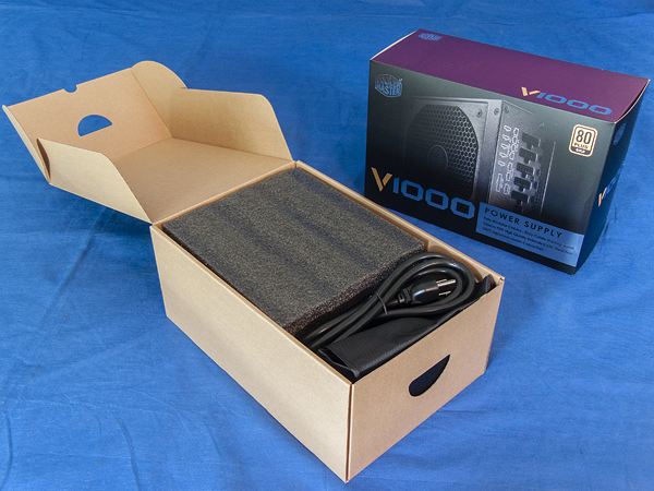
Within the Cooler Master V1000 retail box is another box, containing the surprisingly heavy PSU (surrounded by stiff foam padding,) the AC power cord, and a black bag with all of the modular power cables that plug into or detach from the power supply as needed.
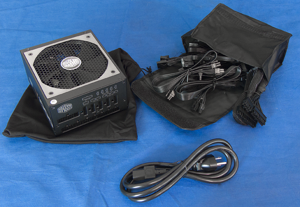
Here's a better look at everything. You can see the big cooling fan lying beneath the PSU's skin as well as the connectors on the front we'll be plugging the ribbon-like cables into later on.
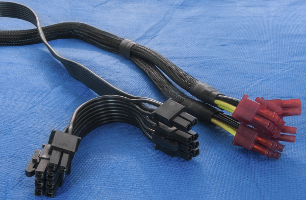
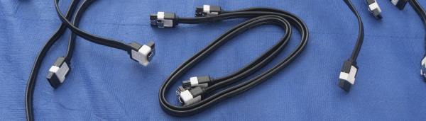
When you directly compare one of the V1000's PCIe cables (left) to a competitor's braided PCIe cable (right), the differences speak for themselves. Both will provide the same amount of power, but Cooler Master has managed to reduce the V1000's cables to be a fraction of the height without being much wider than normal. Beyond the fact that this can be appreciated by novice PC builders, it'll be equally well-regarded by professional modders who often spend hours flattening and braiding their own cables to achieve the same look.
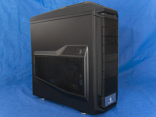
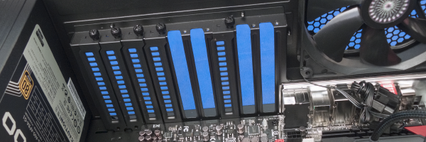
Last up is the case, the Cooler Master Storm Trooper. For being an all-steel case it's rather lightweight, and the rubberized handles on the top/top-rear feel good and solid. Carved into the top of the case is an I/O panel with HD audio jacks, USB ports, an eSATA port, power/reset buttons, and activity LEDs, with a 2.5" drive bay port just beneath. The nine 5.25" bay covers have fiberglass mesh beneath the perforated metal, and there are also removable filters at the top and bottom.
Taking off the side panel (the one visible in the previous photo) reveals a uniformly black interior. On the right side are the two 120mm fans that are paired to the removable and rotatable drive cages, on the ceiling is a 200mm exhaust fan, and at the back is a 140mm exhaust fan. Two 120mm fans can be mounted onto the side panel, as can two more on the floor of the case. The large vents on both of the side panels do not have any fiberglass mesh on the inside, but there are two layers of perforated metal to further assist with reducing dust intake.
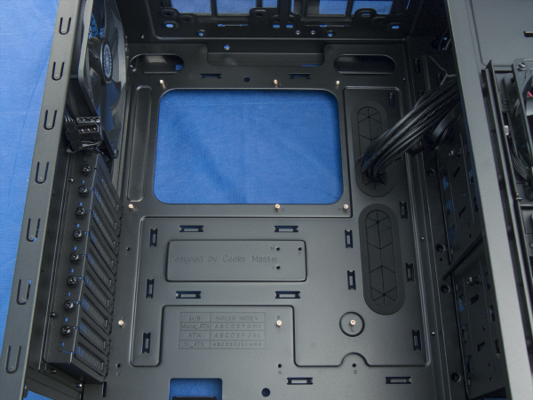
Beneath the other side panel we see the solid black paint job continued and a better view of the drive cages and the cut-outs on the motherboard. The rubber grommets help with hiding and routing cables, while the gaping hole at the top exposes the general region around the back of the CPU socket to ease the process of mounting a heatsink. The cables from the top I/O panel are separated to accommodate different motherboard layouts and user needs since not everyone may want or use the eSATA plug or HD audio/mic jacks. Two power leads come from each of the drive cage fans - one for the fan motor itself and one for the red LEDs - allowing you to leave the fans glowing red or unlit depending on your personal taste.
With our workspace clean and organised, and all of our parts examined, we're ready to begin assembling our system. We'll be stepping through on a component-by-component basis in a way that's as concise and fluid as possible, but if you're in doubt about how to install something, the user manuals that come with your parts often include helpful installation guides to assist you. If you have some concerns or questions that the manuals don't address, feel free to ask fellow gamers and hardware enthusiasts on the GeForce community forums.
Let's get started by removing both side panels since we're going to need constant access to the interior throughout the installation and wiring process. On the Cooler Master Storm Trooper, each panel is secured by two thumbscrews at the rear of the case, and sliding the panel backwards will allow you to remove it. Store both panels and their thumbscrews safely off to the side, where they won't get scratched or kicked or misplaced, and then gently lie the case down on its left side.
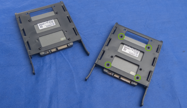
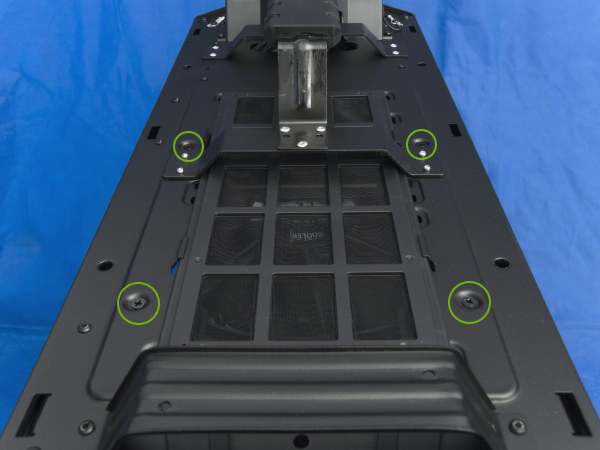
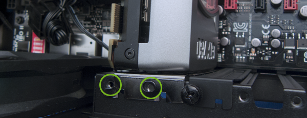
The Storm Trooper has a small drive cage specifically for SSDs at the bottom, but it also comes with tool-less 3.5" HDD trays with mounting points for 2.5" SSDs which can be used to install the Kingston 3K drives in the fan-cooled drive bays at the front of the case. Doing this will also make cable management easier later on. To remove the SSD cage, first slide out the longer air filter on the bottom of the case and then remove the four screws circled below in green. Before you remove the last screw, hold on to the SSD cage with one hand so it doesn't fall and possibly scratch the interior.
With the SSD cage removed, let's fetch the tool-less drive sleds that we'll be mounting the SSDs onto. These are inside of the cardboard box you found inside of the Storm Trooper. We'll need at least two for the 3Ks - more if you're using additional drives for more storage or backup, up to a total of eight between these two cages.
If you're installing a standard 3.5" mechanical HDD, no screws are needed - the drive will be gripped in place by the four small metal pins on the sides of the sled.
There are two groups of mounting points, labeled A and B, which simply affect how far in the sled an SSD lies. Set A (circled in green below) will position the SSD's connectors hanging just off the end of the sled, which will make connecting the power and data cables a bit easier than set B. Each of the 3K drives comes with a small bag containing four screws that are used to mount the drive, but if you're a stickler for color consistency, there also black screws inside of the Storm Trooper's tool tray at the bottom-front of the case that will do the same thing. The mounting points are on the underside of the SSD.
With the drives in their sleds, lift the case back onto its feet and simply slide them into tracks in the drive bays. Use the top drive bay so the power and data cables won't have as much slack when they are connected later.
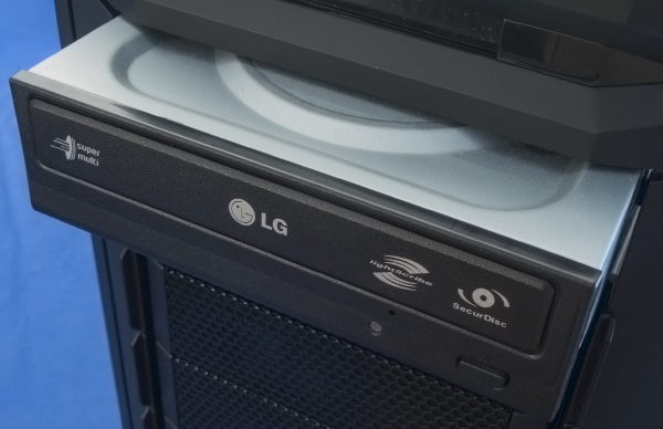
Installing an optical drive is pretty simple: just remove one of the front bay covers and slide it into place. If you’d rather forego an optical drive, you can install Windows 7 and Windows 8 from a USB drive.
Pull off the vanity cover at the bottom of the Storm Trooper's front and you'll see a notch to pull out the tool tray. It's locked in place by two screws, but once it's free, open it up and there will be a baggie full of a ton of screws, a handful of zip ties, an EPS12V extension cable, floppy drive rails wrapped in paper, and a small speaker that allows the motherboard to emit beeping sounds if there's a problem at startup. We'll need two thumbscrews to keep the optical drive in place. They look like the same ones used to secure the side panels.
Align the holes in the drive with the ones circled below, tighten the thumbscrews, and store the drive cover in a place you'll remember in case you ever decide to remove the optical drive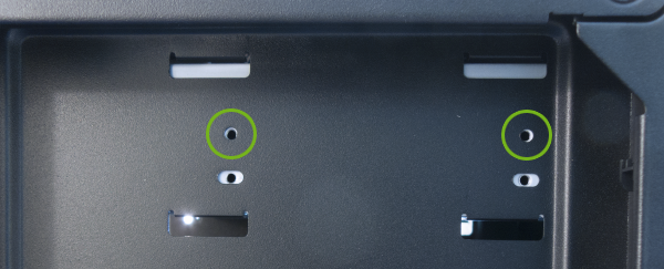
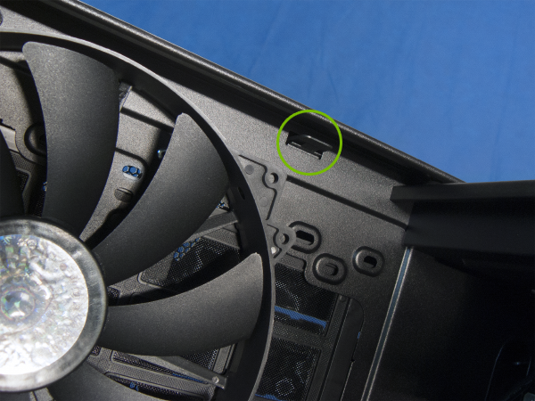
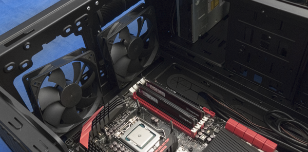
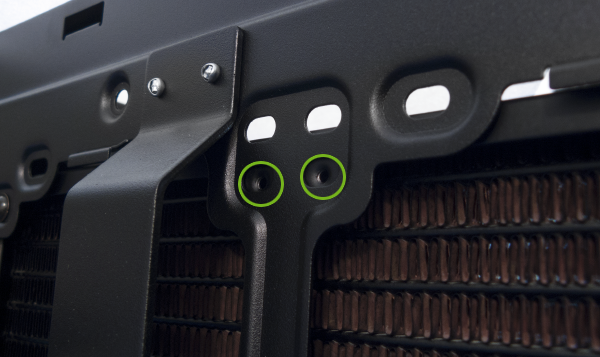
While the case is still on its feet, let's take a moment to detach the top moulding from the Storm Trooper. This will give you access to the screws holding the 200mm exhaust fan to the top of the case, which need to be removed so we can install the Cooler Master Eisberg 240L's radiator and fans later. There are six tabs - three on either side - which have to be pushed out and up. They are not entirely obvious, so here's a look at one in the middle (on the left side if you're facing the front of the case).
Carefully set the top aside and locate the four screws circled below. If you're having trouble with finding the locations of the tabs still, this view should give you a better idea of where they're at. The tabs snap into the rectangular slots along the edge. As before with the SSD cage: when removing the final screw, have one hand holding onto the fan so it doesn't fall and scuff up the paint.
We can't install the Eisberg 240L just yet, so it's time to prep for installing the motherboard. At this point, you can rest the case on its left side. Mixed in the bag of screws that came from the case's drawer are brass standoffs which firmly secure the motherboard to the case's interior. Two are already installed in the Storm Trooper, so we'll need seven more to fully secure the ASUS Maximus VI Extreme since there are nine mounting points on standard ATX motherboards. In the Storm Trooper's bag is also a handy adapter tip which fits a Philips screwdriver and allows you to fully tighten the standoffs, but use this once they've been started and tightened by hand first.
Engraved on the motherboard tray in the Storm Trooper is a useful table which lists the mounting points used by common motherboard form factors (micro ATX, standard ATX, and XL ATX). The Maximus VI Extreme is an ATX-type board, and as per the table, the points we'll be using are: A, B (standoff already installed), C, D, E (already installed), F, J, K, and L. It would also be a good idea to move the bundle of cables coming from the front panel off to the side so nothing will be in the way you lower the motherboard in.
Before lowering in the motherboard, the I/O shield needs to be snapped in first. This is the plate that fits over the ports and jacks that are exposed at the back of the case, so each motherboard will have a shield specifically made for that model. Install the I/O shield from the inside with the writing facing out and the ROG "eye" logo towards the top of the case. It will take a slight bit of pressure, but when finished it will look like this.
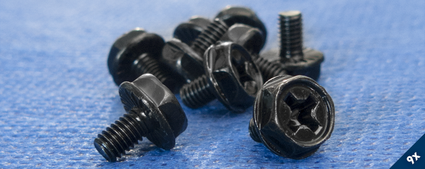
Now we're ready to place the motherboard. Handle it by the edges, hold it vertically until the moment you're about to lower it down into the case, and when setting it down, do your best to align the mounting points with the standoffs. You may have to press down on the screw hole to get the standoff to snap into place. When all of the points have been aligned, grab nine of the black hex cap screws from the Storm Trooper's bag shown below and screw them into the standoffs to secure the motherboard in place.
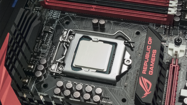
Lift off the black CPU socket cover to expose the metal retention bracket and processor pins below. Do not touch the pins for any reason! Move the latch arm out to the right just enough to allow it to swivel upwards and back towards the top of the case. This will lift up the bracket lid and fully expose the CPU socket.
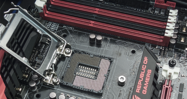
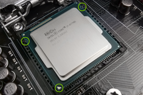
Carefully remove the i7-4770K from its plastic clamshell and hold it only by the corners. On the front of the processor, in the bottom-left corner, is a golden-colored triangle (circled below). This should be pointing towards the red ROG "eye" logo on the black heatsink on the motherboard, below the CPU socket. There are also two semicircular cut-outs on the CPU (also circled below) which will only allow it to be inserted into the socket in one direction. Match these up with the socket and gently lay it flat on top of the pins like below.
Lower the latch arm and socket cover down over the CPU. There won't be any resistance from the latch arm until it's roughly two-thirds of the way down, at which point you'll have to exert a fair bit of pressure to re-lock the arm in place.
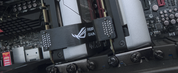
Installing the memory modules is a quick and simple thing, so let's get it out of the way while we're in the area. If you aren't using the same cooler as we are here, this is also a good idea to do before installing the CPU cooler so you can be sure that there won't be any clearance issues. If you're using a different motherboard or memory modules, see the motherboard manual for the proper installation procedure. With the Maximus VI Extreme, we'll be installing the two Kingston memory modules into the black DIMM slots. First, unlock the white tabs circled on the right below by pushing them outward from the slot. Only the tabs at the top need to be unlocked, but other motherboards may require that the bottom tabs to be unlocked too.
Before inserting a memory module into the slot, pay attention to where the "key" is cut in the middle of the slot (also circled below) and on the memory module itself. The key is there so only memory modules of the correct type (DDR, DDR2, DDR3) will fit into a slot when facing the proper direction.
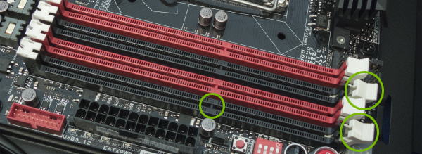
Once the module is correctly placed, apply pressure directly down until it is locked in place by the white tab. Repeat with the remaining module(s).
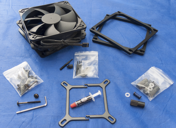
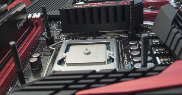
We're nearly ready to install the CPU cooler, but leave the protective film on the copper block for the time being. The Eisberg 240L comes with three sets of screws and bits for different Intel and AMD sockets, but all of what we'll need for the 4770K - threaded rods and inserts, nuts, springs, mount adapter, thermal paste, and the fans - is shown below. Rubber dampeners are also included and are shown to the right of the fans, however due to a clearance issue with the EPS12V plug on the Maximus VI Extreme and the proximity of the radiator in the Cooler Master Storm Trooper they cannot be used. Please note that if you are not using the dampeners, it's possible that the screws used to mount the fans to the radiator will be excessively long - be very careful when tightening these screws as they may be fully threaded into the radiator even though it looks like they still need to be tightened. If this bothers or concerns you, please contact Cooler Master and they will send you a shorter pair of screws at no charge.
Each half of the socket adapter slides into a groove near the base of the Eisberg's CPU block, snapping together at the middle when fully inserted. The threaded inserts snap directly into the four holes around the CPU socket, which you'll then screw the threaded rods into. To fully tighten the rods you'll need to stand the case up, pinch the insert from behind the motherboard, and tighten the rod with your other hand. Once all four are tightly in place, the case can be lied over again. Technically the thermal paste can now be applied, although it would be a good idea to first dampen a small part of a paper towel with isopropyl alcohol and swab the metal surface of the processor. This removes any dust and fingerprint oil that may have been deposited while it was exposed to the air, giving the thermal paste as much contact with the metal heat spreader as possible.
The thermal paste is dispensed from a small syringe. Hover over the centermost point of the processor and apply a portion of the thermal paste roughly one-third the size of a pea.
The pressure that the CPU cooler will exert on the processor face will evenly distribute the thermal paste on its own, but you do have the option of using the edge of a credit card or something similar to lightly flatten the paste out some more. If you choose to do this, don't spread it all the way out to the edge, and keep it as flat as possible - air bubbles between the thermal paste and the CPU cooler will hurt cooling performance.
Prepare the Eisberg 240L by first removing the protective sheet on the copper base of the cooler. As before, it's suggested that this surface is cleaned with isopropyl alcohol. A gentle swabbing is all that's necessary. Some smudges and smears might be apparent, but they aren't going to affect cooling performance. Don't let your hands or anything else touch the base of the cooler while you're handling it.
How you choose to install the fans onto the radiator is a matter of preference: they can either sit above the radiator, effectively pulling air through the fins of the radiator, or they can hang beneath and push air through. The performance for both configurations will essentially be the same, although installing the cooler using the first option (where the fans sit above) is a bit tricky. For the first configuration (fans above the radiator), sit the fans down as shown and try routing their power cables through the holes in the motherboard.
If you prefer the second option, simply mount the fans with the long screws (remembering the warning from earlier) onto the side of the radiator where the tubes are coming out, in the direction indicated by the arrows on the outside of the fan so the air blows out the top of the case.
In either case, first we'll have to remove the dust filter if it's still in place. Beneath it are the screw holes that are needed to align with the middle of the radiator. For the option where the fans sit above the radiator, we'll need eight of the long screws. For the other, we'll need those screws in addition to 8 of the much shorter ones that are found in the same bag.
For those installing the fans above the radiator, feed the long screws through the top of the case and into the holes in the fans so they'll be more in line with the radiator's mounting points.
As noted previously, the long screws used to mount the fans can be too long. There may be a visible amount of excess if yours are. Just to reiterate: Cooler Master has said they are willing to ship out shorter screws to anyone who'd like to have them. At this point, the top dust filter and the top of the case can be put back in place.
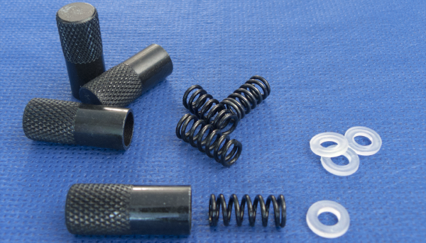
To lock the CPU cooler down onto the processor, we'll need the four knurled nuts (left), springs (middle), and plastic washers (right) included in the packaging.
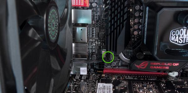
Carefully pick up the CPU cooler, straighten the threaded rods if necessary, align the holes in the socket adapter with the threaded rods, and lower the cooler straight down onto the processor. Don't apply pressure, just keep it in place. Drop a plastic washer down onto each of the threaded rods (so it's sitting on top of the cooler's adapter), followed by one of the springs, and top it with the knurled nut. Tighten these as evenly as possible (three to five turns at a time), then stand the case up on its feet and continue evenly tightening the nuts by hand as you hold onto the back of the threaded inserts like you did earlier. When the cooler is secured, plug the power cable coming out from the cooler onto the set of pins on the motherboard just above the memory slots labeled "CPU_FAN," as you can see circled below.
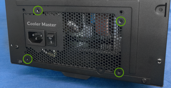
Turning your attention now to the power supply, inside of the V1000's cable bag is a small bag with four black screws. We'll need these to screw the PSU into place.
Position the V1000 so its fan is pointing down so cool air will be brought through the bottom of the case. Tighten the screws into the following holes:
Before continuing, plug the SATA III data cables into the motherboard and the storage and optical drives. It'll be easier to do this now when the graphics cards aren't in the way, and the cables with a 90-degree connector will be ideal to use with the SSDs.
With the metal clip facing up, plug the straight end into one of the red SATA III ports shown below. Use one of the first three sets (starting from the left/top of the picture) so only one set of storage controller drivers has to be installed later, then connect the other end to your storage or optical drive. All devices that use the SATA interface use the same data and power connections, but the cables only attach one way.
Remove the thumbscrews and PCI shields as shown below - the graphics cards will be installed next.
The GTX 780s that use the reference design cooler have a protective plastic film on the shroud window, and this should be removed before they are installed.
Once the file is removed, first press down on the white clip on the right-hand side of the top (red) PCIe slot on the motherboard. Hold the graphics card by the edges and insert it into the slot, pushing straight down until you hear a soft clicking sound. You'll notice the white clip is now in the upright position, which helps keep the graphics card in place. If you need to remove a graphics card, push this clip back down and pull the card straight out.
Return the thumbscrews to their original place to secure the graphics card in its slot, and repeat the same process for the second graphics card. For the Maximus VI Extreme, the second graphics card will be installed into the first black PCIe slot.
With both GTX 780s in place, attach the flexible SLI bridge to one set of the tabs near the thumbscrews. It won't matter which set you use, just as long as the connectors are on the same side. That is, don't connect the bridge to the left tab for the top card and the right tab for the bottom card, or vice versa.
We're in the final phase of assembly! This will be a walk-through of connecting all of the components together and to the power supply, similar to what was done for the installation process - your wires and cables end up may differently than shown here, either due to personal preference or to accommodate differences in hardware, and that's perfectly fine.
In general, cable management is about two things: airflow and aesthetics. The first part is pretty straightforward, since cables that snake and coil up can obstruct or diffuse airflow in a way that might affect the temperature and stability of components. The system should look its best, especially considering that we've invested time and energy into putting it together.
Minimising the presence of the cables is going to be key here, which is where the V1000's ribbon-style cables will show to be particularly desirable when connecting parts visible to the world, but for everything just out of view we'll have to be a little bit more creative: using zip-ties and Velcro to keep bundles neatly together, using empty spaces to conceal excess lengths of cable, and exploiting the amount of space between the motherboard tray and the side panel to conceal the rest. The biggest thing to worry about is making sure that the cables aren't pulled so tightly that connections come loose or pins become bent.
Let's get started with all of the wires for the case's front I/O panel. Feed the bundle of cables through to behind the motherboard, straighten/untangle them, and find the three small wires marked "HDD LED," "POWER SW," and "RESET SW." The first cable powers a small red LED that blinks according to storage drive activity, while the other two make the power and reset switches work properly. These each connect to a specific set of pins on the motherboard, however if you've got an ASUS Maximus VI model, they provide something they call a Q-Connector (shown below with the wires attached) which gives you a simple and easy-to-read layout of the pin arrangements. Connect the wires as shown.
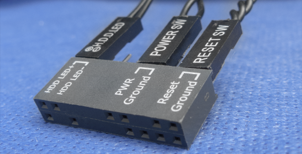
Push the Q-Connector onto the pin header in the bottom-right corner of the motherboard. This can only be inserted one way, so don't use excessive force. If you're using a different motherboard, consult the user manual for its location and the correct orientations for these wires.
Because these cables are twisted and thin they will have a tendency to spread out, so it wouldn't be a bad idea to use the grooves and spaces in the Storm Trooper to help hide the excess cabling. You can do the same for the drive bay fan wires too, and there's even a slot beneath the bottom drive bay where these cables can be fed into to keep them out of the way.
Next, pick out the small USB 2.0 cable and the front panel audio cable. The audio cable has two connectors, one for HD audio (which we'll be using), and another for legacy AC '97 audio. The USB cable plugs into the pin header labeled "USB1112," and there is only one way it can be plugged in.The same is true for the HD audio connector, which plugs into the fan header labeled "AAFP."
After that is the USB 3.0 cable. This has a thick rubberised connector with two cables coming out the back, and it plugs into the red pin header beneath the black 24-pin ATX power plug.
The last cable we'll need from the front panel is the brown and black one with two 3-pin connectors. This will be supplying power to the fans on the Eisberg cooler, and after you've connected these together you can bundle up the remaining unused front panel cables and set them off to the side.
The rear exhaust fan comes with a 4-pin Molex adapter but this won't be needed as there's a 3-pin fan header conveniently positioned on the motherboard, so that can be removed. Plug in the fan's cable into the pin header circled below, labeled "CHA_FAN."
Find the two power cables with "CPU" on one end (EPS12V) and the one thick/wide cable (24-pin ATX). The first two cables will provide the CPU with additional power, while the larger cable provides power to the motherboard which then distributes it to the CPU, its chipset, the memory, the PCIe slots, rear I/O ports, basically everything you see on it.
Plug the split end of the motherboard's power cable into the PSU as indicated by the diagram. The 24-pin connector only fits into the plug on the motherboard one way, and you may have to disconnect the end plugged into the power supply so the cable doesn't twist too much when you find the proper orientation.
The EPS12V cables plug into the power supply's top row of sockets, next to one of the motherboard connectors. There are three EPS12V connections on the motherboard that need to be supplied with power, so one cable will have both prongs in use while the other will just have one plugged in. This will be quite a tight fit, especially if the screws used to hold your Eisberg's radiator/fans in place are too long. If that's the case, push up on the radiator in that corner.
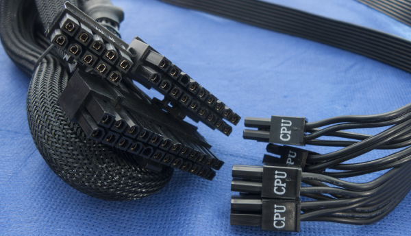
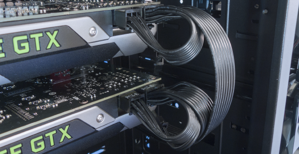
Our GTX 780s each require one 8-pin and one 6-pin power connection. Each of the V1000's "PCI-E" power cables have two of what's called a 6+2 connector - these are common in modern power supplies, and they have the standard 6-pin PCIe connector paired with a 2-pin connector which allows them to behave as an 8-pin PCIe connector when necessary. We'll need two of these power cables for both of the graphics cards, and they plug into sockets on the power supply next to the EPS12V cables.
The data cables have already been attached to the storage drives, and now it's time for the power cables. The SATA power cables look like a wider version of the SATA data cables from earlier, and depending on the hardware you're using, you may need two (or three) of them: one for the storage drives (two if you're using four or more), and another if you're using an optical drive since the first SATA power cable won't reach. Excess cabling can be stored in the empty space inside the drive bay.
We'll also need one cable with the 4-pin Molex connectors. These look the ones found on the rear exhaust fan that you removed a few moments ago. This plugs into the similarly-shaped 4-pin cable that was mixed in with the front panel cables, and provides power for the drive cage fans and a cable we'll be using in a moment. This can't be hidden very well due to cable lengths, but folding and zip-tying the cable can help reduce the size it takes up.
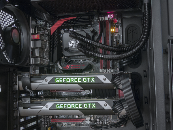
Now would be the time to tidy up any loose cables, because once you're pleased with your cabling, all that's left to plug in is the main power cord going from your home's electrical socket to the back of the power supply. Leave both side panels off for the moment, in case there's any issue when the system is first started up. Flip the switch on the power supply so it's in the "I" position, let it build up a charge for a moment, take a deep breath, and press the power button on the top of the case.
If everything has been connected correctly, and all the parts are in working order, the moment you depress the power button you'll be bathed in a green glow from your GTX 780s and hear the whisper of the fans over a humming water pump. Congratulations! You've built your own high-powered SLI gaming PC!
Just after a moment of worthy celebration passes, you might notice the computer then turns itself off. It's a bewildering and heart-sinking thing to see, but know that this is the motherboard's way of checking hardware and overclocking parameters to make sure nothing has gone wrong (or is wrong) with the current configuration. When it finds that everything is order, your PC will resurrect itself back to full life.
As the Maximus VI Extreme iterates through its list of initialising different components, it will do like many other motherboards do and print out a code (referred to in the user manual as "Q-Code") on a small, red display in the top-right corner. This is very useful as it allows the motherboard to tell you specifically what, if anything, has gone wrong without necessarily having to connect a monitor to the computer. Consult your motherboard's user manual for its table of codes and definitions, especially if it seems like something isn't right with how it's starting up. It should give you some insight as to what the problem may be.
There is a chance that, for some reason, your computer doesn't start up. This will require you to double-check power and wire connections like those leading from the front panel to the motherboard, the various power connections feeding the motherboard and all of the other components, the connections going into the power supply, the AC power cable at the rear of the power supply, and the power switch beside it. These things may have been bumped out of place while hooking up other cables or were only partially connected to begin with. If your problem continues to persist, please ask the GeForce community for assistance, ask a computer literate friend, or if all else fails try contacting your local computer repair shop.
Wow! We've covered a LOT of material here today, but we're only halfway through! Next week we'll enter the software side of things - taking a look around the BIOS, installing your operating system, finding the right set of GeForce graphics drivers, navigating the NVIDIA Control Panel, tweaking application profiles, grabbing a few essential utilities and programs like GeForce Experience, and wrapping up with some good benchmarking practices. Stay tuned!